Slabs - Design Cuts
Design cuts are used to look at areas of interest or concern within a slab, or to investigate specific critical locations that may be difficult to define with a design strip. They can also be used to double-check design strip results, as design strip results typically show the envelope of the worst case moments in the whole strip. A design cut is defined by drawing the cut plane from a start point to an end point. The total moment about the cut is computed from the underlying finite element results. This moment is then used to calculate the required area of steel and the number of bars required to satisfy that area of steel. The bars used to resist the moment will be perpendicular to the design cut. Care should be taken when drawing a design cut to only include the area of interest.
Create Design Cuts
Design cuts may be defined either before or after a solution is performed.
To create a Design Cut:
- Select the Design Cut tool from the context menu by right-clicking within a 3D Model View.
- Click two points to define the start and end of your design cut.
- A design cut will be shown on the screen as a green dashed line, and you will see a new Design Cut definition show up in the Design Cut spreadsheet.
Design Cuts Spreadsheet
As you draw design cuts, they are automatically entered into the Design Cut Spreadsheet, which can be accessed by selecting Design Strips/Cuts from the Data Entry drop-down on the Spreadsheets tab of the ribbon, or by clicking Design Strips/Cuts from the Data Entry section of the Explorer panel.
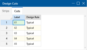
Click on image to enlarge it
You can modify the Label and the Design Rule used to compute the reinforcing bars. You cannot modify the Start and End points of a design cut. If you need to move a design cut, you will need to delete it and redraw it in the new location.
Label
You may assign a unique label to each design cut. Entering a duplicate label will result in an error message.
Design Rule
The Design Rule used for each design cut defines the parameters used to calculate the required area of steel and the reinforcing bars. For more information on Design Rules, see Design Optimization.
Design Cut Results Spreadsheet
The summary results for all your Design Cuts can be seen in the Design Cut Results Spreadsheet. To view the design cuts results spreadsheet, click Results Browser from the Results toolbar and select Design Strip/Cut Results. Or, click Design Strip/Cut Results in the Results section of the Explorer panel.
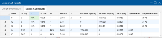
Click on image to enlarge it
The spreadsheet results let you quickly see the Unity Checks and Shear Checks along with the moment capacity and number of bars required in the top and bottom of the slab for your design cuts.
Design Cut Detail Report
Additional results information can be obtained by viewing the Detail Report for a design cut. To access this report, select Detailed Report from the Results toolbar and then click the design cut you want to review. The Detail Report gives additional information about the design cut properties and provides many of the supplementary values to help check the results. Information in the Detail Report will vary depending on whether the design cut was auto-generated for a design strip or was a custom design cut created by the user. The information in a user created design cut will be limited. Below, we will walk through each section of the report for a design cut generated for a design strip.
Header

Click on image to enlarge it
The header of the Detail Report is useful for navigating and viewing information in the design cut reports.
- The arrows allow you to click through detail reports for the different design cuts in the model.
Input Data

Click on image to enlarge it
The first section of the Detail Report merely echoes back basic input data, such as the starting and ending locations of the design cut, the basic Design Rule parameter, the type of stress block used and the material type for the slab.
Code Check Data

Click on image to enlarge it
The information in this section is intended to give the basic data used in the code checking of the concrete section. This includes the demand moment (Mu) and capacity (Mn) when the top or bottom bars are in tension. This section also reports the one-way shear demand (Vu) and capacity (Vn).
Area of Steel Required
The program calculates the area steel required based on the steps listed below.
Step 1 (Analysis): Calculate the area steel required by analysis. Select a spacing and number of bars that fit the design region.
Step 2 (Min Flex): Check that the minimum reinforcement for flexure is being met per ACI 318-14 Section 8.6.1 (ACI 318-11 Section 10.5, CSA A23.3-14 Section 10.5.1.2).
Step 3 (4/3): Check the 4/3*As required by analysis per ACI 318-11 Section 10.5.3, CSA A23.3-14 Section 10.5.1.3.
Reinforcement Design Routine
Since a design strip has multiple cuts, we need to first consider each cut and then take the enveloped value for the cuts for the overall strip.
For each design cut:
- Calculate As Req’d to satisfy all provisions (Strength, T&S, Min_Flex, 4/3*Strength).
- Calculate an integer number of bars (or an equivalent number of bars if Theoretical Method is selected in the Rebar tab in Model Setting) that meets or exceeds As Req’d from Step 1.
- Calculate a number of spaces (equals Step 2 value minus 1).
- Spacing = Divide cut width by Number of spaces (from Step 3). This will almost always be a decimal value.
- Calculate Min_Spacing as the greater of ACI min spacing requirements (2*db, etc) and Min Spacing from Design Rules.
- Calculate Max_Spacing as the lesser of ACI min spacing requirements (6*db, etc) and Max Spacing from Design Rules.
- If Min_Spacing < Spacing < Max_Spacing.
- Round Spacing down to closest value divisible by Increment (Increment comes from Design Rules). Report this as your Spacing value. Do not adjust As.
- If Spacing > Max_Spacing.
- Calculate the lowest integer number of bars which satisfies Max spacing.
- Calculate a number of spaces (equals number from Step 8.1 minus 1).
- Spacing = Divide cut width by number of spaces from Step 8.2.
- Round Spacing down to closest value divisible by Increment (Increment comes from Design Rules). Report this as your Spacing value. Report As from Step 1.
- If Spacing < Min_Spacing.
- Calculate the lowest integer number of bars which satisfies Min spacing.
- Calculate a number of spaces (equals number from Step 9.1 minus 1).
- Spacing = Divide cut width by number of spaces from Step 9.2.
Report Decimal Spacing. The cut will fail anyway because Req’d spacing was below what’s allowed. Report As from Step 1.
Once this is complete, we have a rebar spacing and As for each cut.
Then report the smallest value of Spacing from all of the design cuts for each design strip.
Single Layer Rebar Design
The single layer rebar option allows the user to specify one layer of rebar at any depth in the slab. The location of the rebar in the slab is controlled by the top cover input in the Design Rules. This option especially benefits the design of thinner and lightly loaded slabs on grade where two layers of reinforcement may be too complex and/ or unnecessary. The single layer rebar uses the design routine above to determine how much steel is required, with the addition of the following assumptions:
- If the single layer is placed at or above mid-depth, the one layer of rebar is assumed to resist both the positive and negative bending.
- If the single layer is placed below mid-depth, the layer of rebar is only assumed to resist the bottom moment. Any top moment will be compared against the plain concrete capacity according to ACI 318-14 Equation 14.5.2.1a (ACI 318-11 equation 22-2).
Cross Section Detailing
This section provides a visual verification of the bar arrangement, slab thickness and cover. Depending on the Mat Slab Design Option selected in the Concrete tab of Model Settings, the Cross Section Detailing can be different.
If the Construction Method is selected, the cross section will show the actual rebar amount:

Click on image to enlarge it
If the Theoretical Method is selected, the cross section will show a generic view and the rebar displayed are for reference only. We do not show the rebar amount because the rebar calculation is based on average rebar area and the rebar amount may not be an integer:

Click on image to enlarge it